You are using an out of date browser. It may not display this or other websites correctly.
You should upgrade or use an alternative browser.
You should upgrade or use an alternative browser.
DIY Head Tracker For A Tenner
- Thread starter Dead Fred
- Start date
Anyone have a video of this in action? Ordered one yesterday, should be here in a week or two, would love to see how it functions.
Try this, I'm the one in the picture in the corner and seem to move my head around and extraordinary amount. Brumster is also using one (kinda obvious I guess)
https://www.youtube.com/watch?v=ZBkP1QaKuBM
Try this, I'm the one in the picture in the corner and seem to move my head around and extraordinary amount. Brumster is also using one (kinda obvious I guess)
https://www.youtube.com/watch?v=ZBkP1QaKuBM
Awesome, thanks!
You surely have to way too much spare time...
LMAO
LMAO
This makes a device which appears to Windows as a Three axis joystick that you put on your headset to track head orientation. The hardware is capable of Six degrees of freedom. At present ED only allows access to two axes for headtracking unless you are Oculus Rift or Naturalpoint Inc.
paste: 15/6/ 2014.
End of paste:
My preferred method of attachment is a couple of nine inch nails, acupuncture style....
This does have some interesting psychological side effects, but hey, what are Alpha testers for?
There are some physiological ones aswell but after a few hours you get used to it. Then you start to notice when you can't track a target properly because you can't look around. You feel disadvantaged.
It is very useful for when you are trying to find the station entrance but you are very close to the station, just look up, you don't have to crash into the station to find out where it is.
Also when running noob cannons you can get a gimbal lock when otherwise you would not be firing because you don't know your gimbals have the target.
So we are trying to do it on the cheap such that the rich kids don't win all the time because of better situational awareness.
It is also quite enabling for people who don't have the use of their limbs.
Most of the questions I see below, have been experienced and beaten and won in the Alpha version of this thread.
It's a shame we can't just merge them now.
It's a bit like déjà vu. We see the same thought processes happening again. It's quite lovely.
I have seen your question before......
However, I digress.
After the initial calibration and upload you don't need the Arduino IDE anymore, to windows it's just a new joystick. But its nice to keep the serial monitor open so you can see the numbers changing as you move your head around if you have not commented out the debug line. In fact if you leave the debug line in and don't monitor it, you end up with a fifo overflow and it stops working. But its good to have it all installed so you can upload new software to the ProMicro as it is developed.


Pocketmoon wrote :
You will need the latest beta of the Arduino IDE , which at the moment is 1.5.6 r2. You can use the latest stable release but you need to use the right version of USBAPI.h from githib/pocketmoon
https://github.com/pocketmoon/MPU-6050-Arduino-Micro-Head-Tracker/tree/master/Arduino Library
Just rename USBAPI.h..105 to USBAPI.h
It does involve a bit of intelligence and soldering but we want to get it to the stage where it is as easy as possible. If you can't be bothered then when the production boards arrive we can make finished, programmed and calibrated units available.
The next thing to do will be to design a box to put it all in and remove stress from the micro USB port on the ProMicro.
We were thinking of making a Cobra shaped 3D print with light guides so it looks like the engines and weapons are firing. That's version Two or Three.
We are still at sort of nearly V1. Maybe, possibly and perhaps.....
Here is a link to Brumsters Fantastic PDF showing you how to do it.
http://www.brumster.com/downloads.php?cat_id=1&download_id=3
The code.
http://reprapdad.wordpress.com/
and indirectly
https://github.com/pocketmoon
The Latest version 2 code "For The Brave"Includes a nice little UI which is unfinished but really helps you see what is going on. Also the code uses different libraries which solve some problems we were having.
http://reprapdad.wordpress.com/2014/05/13/ed-tracker-v2-for-the-brave/
Brumster's Vid part 1.
https://www.youtube.com/watch?v=_oqLwCtMCKc
and part 2
https://www.youtube.com/watch?v=m4hyMbHpl18
This is what we are doing in Alphaland.. Fiddling mostly. The code you can download is ace and is being improved all the time. There is also a nice User Interface being developed (with a big spinny head) reducing the need for setting up the Arduino IDE, it also lets you see what is going on much more easily.
The drift is fixed. We fixed it. Mostly.... And we continue to fix it.
Though there are a number of ways to kill it completely using extra hardware(magnetometer, cameras and lights etc) But I think we can do it without extra hardware. I have been talking to the others about deriving a known good forward position using only the information we have.
If we can crack that properly.........
Its all there too see, you just have to see it.
Sorry for the new thread Blue Peter headset guys, I gave it the same name as the Alpha thread for commonality.
While point based tracking does work. I believe this is a more elegant solution that does not depend on room lighting or mind if there is a heater behind you etc. The processing overhead is removed and its probably more accurate (16 bit precision) and has lower latency. It's so low you can't detect it.
It's cheap and it's open source.
Assembly Video.
https://www.youtube.com/watch?v=-tF0Yrim0mo&list=UUhhdxi3tHTrmpB4y4m3i0GA
Flashing/ programming video
https://www.youtube.com/watch?v=Jn53ZHI7rHw&feature=youtu.be
So we have gone from this.

To this.


The double sided surface mount version will arrive in time and that will be smaller still. Then we can make a box for it.
I can't mount mine on the top very easily because my headset is hinged there so I just sticky pad mounted the USB cable at the top. When in use it's much flatter and seems to work fine.

I got mine working today, after someone in the other thread pointed out that a Kindle has the correct connector.
I had a bit of trouble at first with a flashing yellow light and the device not being detected by either of the UI programs even though the driver had been installed after auto-detection. I'm not really sure what sorted this as I was moving it about a bit and may have adjusted the USB connector on the board.
Can anyone confirm what lights they have on under normal operation? I have a green, red and occasionally a yellow light (solid now) on.
I've just got a drift issue to sort out now (between 5 and 6) so I. Assuming I may need to re flash the device?
Another quick question, the PDF instructions say to press '9' to make the dots on the 'target' head towards the middle. However, the options in my UI (32-bit...Java version?) only go up to 8.
I couldn't resist a quick go in game but think I may need some tweaking as I have to turn my head quite a ways to get to the sides.
Still, early days...well chuffed with it so far.
I got mine working today, after someone in the other thread pointed out that a Kindle has the correct connector.
I had a bit of trouble at first with a flashing yellow light and the device not being detected by either of the UI programs even though the driver had been installed after auto-detection. I'm not really sure what sorted this as I was moving it about a bit and may have adjusted the USB connector on the board.
Can anyone confirm what lights they have on under normal operation? I have a green, red and occasionally a yellow light (solid now) on.
I've just got a drift issue to sort out now (between 5 and 6) so I. Assuming I may need to re flash the device?
Another quick question, the PDF instructions say to press '9' to make the dots on the 'target' head towards the middle. However, the options in my UI (32-bit...Java version?) only go up to 8.
I couldn't resist a quick go in game but think I may need some tweaking as I have to turn my head quite a ways to get to the sides.
Still, early days...well chuffed with it so far.
Can't tell you the colours of the light as every Arduino seems to have different LEDs fitted. But you will have two on the Arduino and one on the MPU-6050.
But for one running an ED Tracker sketch.
The MPU one will light up when it is powered up
On the Arduino both will turn on when its powered up, one constantly on the other flashing very fast.
After the 10 seconds for boot up the constantly on one should turn off and the flashing one will slow down.
First of all I'd like to thank all of the edtracker team, the edtracker works great. Unfortunately its use has resulted in more scratched paint and hefty insurance bills because I've not been watching where I'm going.
One thing I did have trouble with was getting the initial sketches loaded, it turned out I needed to reset the boot loader as described here.https://learn.sparkfun.com/tutorials/pro-micro--fio-v3-hookup-guide/all#troubleshooting-and-faq.
Enjoy the edtracker, but remember watch where you're going.
One thing I did have trouble with was getting the initial sketches loaded, it turned out I needed to reset the boot loader as described here.https://learn.sparkfun.com/tutorials/pro-micro--fio-v3-hookup-guide/all#troubleshooting-and-faq.
Enjoy the edtracker, but remember watch where you're going.
Can't tell you the colours of the light as every Arduino seems to have different LEDs fitted. But you will have two on the Arduino and one on the MPU-6050.
<snip>
Thanks for the info. I'll try and figure out a pattern but what you describe seems similar.
Hey, just wanted to give an update to the earlier test for the 3v3/8MHz version of the Pro Micro board.
I thought it was a little odd that it worked but gave glitchy readings, so I dropped the DEFAULT_MPU_HZ to 50 and it seems much more stable. That's a bit low, but I don't seem to be able to notice it when playing the game.
Nick
I thought it was a little odd that it worked but gave glitchy readings, so I dropped the DEFAULT_MPU_HZ to 50 and it seems much more stable. That's a bit low, but I don't seem to be able to notice it when playing the game.
Nick
Last edited:
Might this one not be an alternative fit? It's 1cm longer so would mean the board wouldn't need chopping?For anyone looking for a simple way to case the final ED Tracker, this is what I came up with using a "mini ABS" project box from Maplins.
The part numbers for the boxes are "SC782 for the grey and "N78BQ" for the black

The push button hole is about 8mm and tapered just enough to allow me to reach the switch.

The USB plug fits into the box so you might need to take out more of the sides than I did for my cable. Also removed the two PCB board mounting post in the main box to allow clearance for the unit.

Had to remove the opposite two corners to allow the main PCB board to fit in between the two screw mounts. You could cut them away if you plan to glue the cover on.
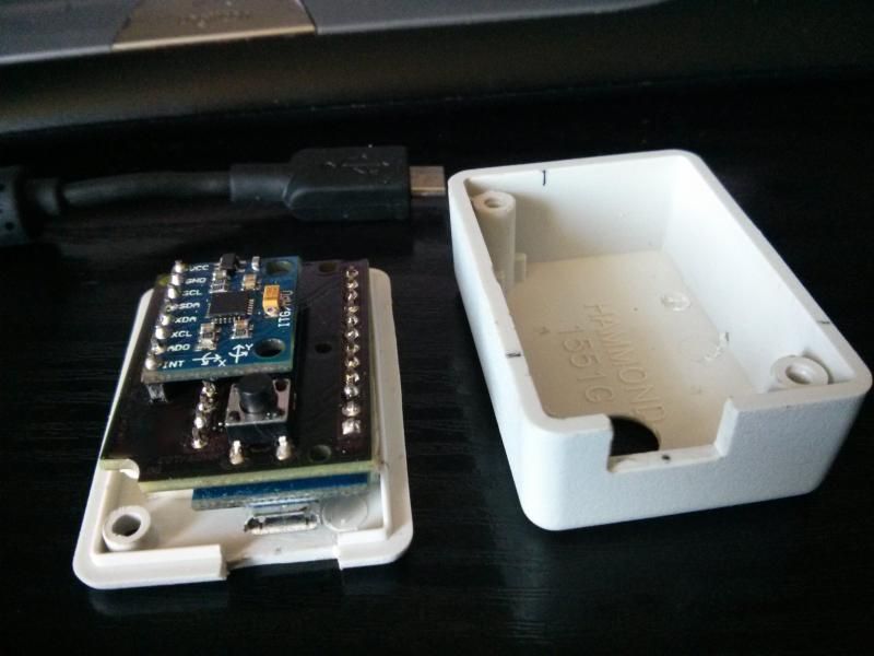
Used double sided sticky foam to hold the unit to the cover to stop it moving about.
The final thing will be to use Velcro on the lid which is to be the base of the unit so it can be attached to my headphones.
http://www.maplin.co.uk/p/hammond-m...se-abs-box-1551-series-black-60x35x17mm-n79bq
Here's your original 5cm suggestion - http://www.maplin.co.uk/p/hammond-m...se-abs-box-1551-series-black-50x35x17mm-n78bq
I used a tic tac box in the end. It works really well.
I have to try this. :smilie:
At the moment, it's attached to my headphones with a Velcro cable tie. Well, two...the second to put a loop in the cable to take the stress from the USB socket.
How did you attach it inside the tic tac box to stop it rattling round? And how easy was it to make a hole for the button without shattering the box?
Did you drill a hole for the button?I used a tic tac box in the end. It works really well.
Not quite as perfect in size as Omegahunter's box(es)? - http://forums.frontier.co.uk/showpost.php?p=534515&postcount=1191
What flavour tic-tacs?
EDIT: Tic Tac dimension I believe are:-
Ext Height=64.5mm=2.54in (without lid)
Int Height=62mm
Lid intrudes into box 15mm
Ext width=40.9mm
Int Width=39.4mm
Ext Depth=16mm
Int Depth=15.1mm
Int Height=62mm
Lid intrudes into box 15mm
Ext width=40.9mm
Int Width=39.4mm
Ext Depth=16mm
Int Depth=15.1mm
Isn't the internet great!
Last edited:
Here you go, picture below.
https://docs.google.com/file/d/0BxQGA10kgouDeHhWbHFiNFFVS28/edit?usp=docslist_api
https://docs.google.com/file/d/0BxQGA10kgouDeHhWbHFiNFFVS28/edit?usp=docslist_api
Here you go, picture below.
https://docs.google.com/file/d/0BxQGA10kgouDeHhWbHFiNFFVS28/edit?usp=docslist_api
Excellent...looks like a modded PC case with all the lights!
Here you go, picture below.
https://docs.google.com/file/d/0BxQGA10kgouDeHhWbHFiNFFVS28/edit?usp=docslist_api
Interesting how your button comes out a long way, while on Omegahunter's (same height box) it doesn't?