DIY Head Tracker For A Tenner

You have a power LED on the GY module and the Arduino; you then should have a flashing light on the Arduino which is just the EDTracker code showing you that it's working. So you sound all good ;) ....

Thanks for the quick and informative response brumster, much appreciated :D
 
So I did some soldering and finished my tracker with a MPU-9150 unit. It works quite well, with the button under the (flexible) lid:
30.jpg

Only problem is the drift - in the calibration value it is highly dependend on the position of the device (also temperature): Calibration seems to be valid only for one orientation. Also, the green and orange dot seem to stay in the center only for that specific orientation.
Is that normal behaviour or am I doing something wrong? I'll have to try the latest version of the firmware.
 
Oh and if it can handle being soldered then yes it should be fine with hot glue.

that's the bit I was trying to get to I have a box and im now going to seal the whole gubbins in it cable joint and all with hot glue wish me luck
like the hairband idea tho ( mmmm pretty in pink that may raise a smile from the SO till she works out its one of hers )
many thanks
dave
;)
 
that's the bit I was trying to get to I have a box and im now going to seal the whole gubbins in it cable joint and all with hot glue wish me luck
like the hairband idea tho ( mmmm pretty in pink that may raise a smile from the SO till she works out its one of hers )
many thanks
dave
;)

Sounds like a plan to me, once you've ensured it's working right of course. I don't think you need to fill the whole thing with hot glue, just run a bead around the edges of the PCB to lock it in place... and around the hole your USB lead's going through. I'd still suggest some sort of mechanical strain relief for the cable like a cable tie or similar too, just to stop the plug & socket getting pulled around if the cable gets pulled.

Hehe I'm sure you can find one in basic black like I did. :D
 
So I did some soldering and finished my tracker with a MPU-9150 unit. It works quite well, with the button under the (flexible) lid:
30.jpg

I really like that box you've got it mounted in - where'd you find it?

Only problem is the drift - in the calibration value it is highly dependend on the position of the device (also temperature): Calibration seems to be valid only for one orientation. Also, the green and orange dot seem to stay in the center only for that specific orientation.
Is that normal behaviour or am I doing something wrong? I'll have to try the latest version of the firmware.

The amount of drift is VERY temperature dependant... you should plug it in and leave it sit for at least 15 minutes to warm itself up before you calibrate it, then when you've reset the drift make sure you leave it at least another 15 minutes before you save the drift compensation value. If the value's not between -0.1 and 0.1 then run it again.

I leave mine plugged into the PC all the time so it stays at running temperature, so I don't have to worry about drift when it's cold.
 
In general I like the idea of sandwiched boards for ease of assembly.
But in this case, the resulting package is too high in my eyes.

Remember that pile of dead USB sticks you're reluctant to throw away?

First fitting:
e6xf2f.jpg

Some Dremel work for the button:
1e71ia.jpg

Soldering done:
2qu3kgw.jpg

Glued into place with friend epoxy:
mjbpe0.jpg

Et voila, instant EDTracker:
2eel82b.jpg
20usb9v.jpg

Works like a charm.

I am so happy right now!
I can't thank you guys enough for the time and work you put into this project. And since this is now officially part of the english language, amazeballs!

How's the sensor fusion output coming along? :D
 
Unfortunately, I've had to disconnect mine for the time being. I just can't seem to stabilise the drift, no matter how many times I try the calibration and/or drift compensation steps. I've even gone so far as to wipe the EEPROM and start from scratch but with no discernible improvement. One thing I've not been able to get around, is that the device is a couple of degrees warmer when it's on my head(set) than when I'm calibrating it. Without clamping my head in place for half an hour, I'm not sure what I can do about this. Could this be a factor? I do have a new headset incoming which has thicker padding, so this might not be an issue in the future.

In game, I'm finding I have to press the reset button every minute or so to counter the drift to the left...even with dead zones and the auto-centering. Don't get me started on the docking/galaxy map, jump to the left, problems. However, I believe this is a game issue rather than the tracker.

One thought I had is that I recently got an X55 Hotas which is using an additional two USB slots. Does anyone know if it could be a power level issue? I know the Hotas itself has a few problems in the area, with calibration.

Thanks for any help.

I don't think it could be a power level issue, since the pro micro has an onboard regulator ( http://www.micrel.com/_PDF/mic5219.pdf ) that supplies the 6050/9150. Even if the USB voltage drops a bit this thing should do the job.
If you know how to use a multimeter it never hurts to check, though.

Did you look how the tracker works in the gamecontroller settings from Windows?

For calibration and drift compensation try to use a flat surface and clamp/tape it down. Put the cable in straight, so as to not put any force in any direction on your device.
Don't use the table your computer sits under, as minute vibrations from fans etc. can translate to the table. Calibration worked better for me once I realized that.
Enclose it in something, so that what little heat is generated isn't lost quickly. This might give you a degree or two over half an hour.

Good luck.
 
I'd like to ask again:
Is it normal behaviour that drift is very dependend on orientation of the device?

I get minimal drift (<0.1) when calibrating the device lying flat on the table. Then, when tilt it ~20° and watch the readouts, I get a drift of about 10 units (whatever units they are).

Obviously, this renders calibration more or less useless because unfortunately I can't (and don't want to) keep my head perfectly leveled all the time.

I'll assume by calibration, you mean just calculating the yaw drift (not the accel/gyro offset calibration)?

If so, you must calibrate yaw drift with the device in the same position as you intend to use it, but a 20 degree tilt doesn't sound like a suitable position to me. It sounds to me you've calculated yaw drift with it flat but then moved/mounted it to a different position.

Easiest thing, if it's possible, is to mount the device how you intend to use it and THEN do the yaw drift calculation. Of course, you've got to hold it very still while in this position :) ! Available positions are top and side mounts, with the USB cable coming out in a variety of directions (see the options in the GUI tool).

Hopefully that's all the problem is.
 
Easiest thing, if it's possible, is to mount the device how you intend to use it and THEN do the yaw drift calculation. Of course, you've got to hold it very still while in this position :)

And please remember, you don't have to mount it on your head for the calibration process... no-one expects you to keep your head still for 15 minutes. Get a coffee can or something and sit that on your desk with your unit mounted on that. :)
 
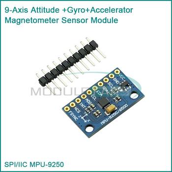
Ordered a MPU-9250 (http://www.invensense.com/mems/gyro/mpu9250.html)
and a Arduino pro mini ATmega32u4 to see if it will work with TrackED V2.

sku_303804_1.jpg


Features

  • Digital-output 6-axis MotionFusion data from DMP. 9-axis fused data from Motion Processing Library
  • Tri-Axis angular rate sensor (gyro) with full-scale range of ±250, ±500, ±1000, and ±2000dps
  • Tri-Axis accelerometer with a programmable full scale range of ±2g, ±4g, ±8g and ±16g
  • Tri-axis compass with a full scale range of ±4800µT
  • Reduced settling effects and sensor drift by elimination of board-level cross-axis alignment errors between accelerometer, gyroscope, and compass


Hopefully I can get this running with with TrackED, would it take much to get the software to run full 6DOF for use with other games that support full 6DOF.

Built a PS3 based 6DOF IR tracking unit, but like the idea of the precision that these chipsets offer.
 
Last edited:
I hope that's a typo - the Pro-Mini uses an ATmega168 with no USB socket.
You want an Arduino Pro-Micro like this one.

Sorry yes, was a typo. Once I confirm it works I will most likely design a atmega32-u4 based smd board to get the footprint as small as possible.


Has 10 pins compared to the 6050 and 9150 which mostly come with 8 pins.
Chose this one since the first 8 pins are named exactly the same as the 6050. Hopefully that will allow the current software to work.

SPI-IIC-MPU9250-MPU-9250-MPU-9250-9-Axis-Attitude-Gyro-Accelerator-Magnetometer-Sensor-Module-MPU9250.jpg_350x350.jpg


It should work fine, the extra 2 pins are the aux SDA and SDL pins for the i2c comms with the mag sensor.
 
Last edited:
Ordered a MPU-9250 (http://www.invensense.com/mems/gyro/mpu9250.html)
and a Arduino pro mini ATmega32u4 to see if it will work with TrackED V2.

sku_303804_1.jpg


Features

  • Digital-output 6-axis MotionFusion data from DMP. 9-axis fused data from Motion Processing Library
  • Tri-Axis angular rate sensor (gyro) with full-scale range of ±250, ±500, ±1000, and ±2000dps
  • Tri-Axis accelerometer with a programmable full scale range of ±2g, ±4g, ±8g and ±16g
  • Tri-axis compass with a full scale range of ±4800µT
  • Reduced settling effects and sensor drift by elimination of board-level cross-axis alignment errors between accelerometer, gyroscope, and compass


Hopefully I can get this running with with TrackED, would it take much to get the software to run full 6DOF for use with other games that support full 6DOF.

Built a PS3 based 6DOF IR tracking unit, but like the idea of the precision that these chipsets offer.

The MPU-6050 already is 6DoF. You can then fuse the magnetometer in software as above but you'd still only get orientation!
 
Back
Top Bottom