DIY Head Tracker For A Tenner

Hi guys, very pleased with my 9150, however it's developed an odd glitch. When I tilt my head back to look up, the view will also yaw to the left with a slight lag after the pitch. I get the same but to the right when I look down. I've tried redoing the magnetometer and gyro set up but no improvement.

I use opentrack, and the mapping function shows the above inputs come from the EDtracker.

Any ideas?
 
Just to say, this has worked brilliantly for me, bought the components mail order last week, took 30 minuts to solder 7 connections using ribbon cable. For simplicity I used heat shrink tubing to insulate the 9150 sensor and to encase everything, the button was hot melt glued on top. Finally some velcro ontop of my headphones and secure with a velcro strap.
Worked straight away and was easy to calibrate and set up. Must say the drift is just about non existant, left my headphones on the desk for over an hour, still centalised when I started up again!
Nice and compact with no led gizmo required, well done there and the low cost is a huge bonus :)
 
Hi guys, very pleased with my 9150, however it's developed an odd glitch. When I tilt my head back to look up, the view will also yaw to the left with a slight lag after the pitch. I get the same but to the right when I look down. I've tried redoing the magnetometer and gyro set up but no improvement.

I use opentrack, and the mapping function shows the above inputs come from the EDtracker.

Any ideas?
Sounds like orientation is wrong, but this might be a bug. Try some different orientations and see if that fixed it. USB Left should work fine, don't worry too much about axes being the wrong way round as it doesn't really matter, you just map them opposite if your USB cable is actually come out of the right. Give that a try and let me know; I have a sneaky suspicion some of the orientations are wrong. Rob? Comment?
 
Got my 9150 yesterday, and it works like a charm with Elite Dangerous!

Like Blairvoyach, I added some X to the Yaw in Opentrack and it worked in IL-2 Sturmovik 1946 for a while, but then the whole headtracking froze up. I have the CH Throttle ministick unused when flying WW2 birds, so I think I'll try mapping the ministick for X and Y next.
 
I seem to have broken my 9150. it was working fine, but today when I tried it was not working.

Symptoms:
Red light steady on Arduino, green light on 9150. No other lights flashing as they normally do.
You can flash it. Once flashed, it does not go to the normal 9150 calibration on the GUI.
Tried disabling/enabling com ports etc.
Checked connections on the device - the lines between the arduino and the 9150 beep out okay. Checked all solder joints - all seem fine.
Its inside a hammond box for protection.

So, considering it was working fine yesterday, it flashes (showing the USB is fine), my guess is that the 9150 has given up the ghost. Has anyone else has 9150 go out on them?

My old 6050 works fine.

Is there any other debugging I can do?

Cheers
 
If the GUI "connects" but just doesn't show any movement (all values at zero or 62.75), no values changing just solid, but the graphs are trundling along nicely, then it does indeed suggest that the comms between the AVR and the MPU have given up the ghost. You could try putting the 6050 code into it temporarily just to see if that has any better luck, not really as a long-term solution but just to understand what aspects of the chip may not be working. But short of getting a DSO on the i2c lines, it's just the usual checking really :( which sounds like you've already done
 
Have you got any advice for swapping out the boards? I managed to rip the USB socket off the Arduino and it was a right PITA replacing it because of the number of pins, even using a desoldering pump I couldn't release the Arduino from the ED tracker board - I ended up carving up the Arduino with a Dremel saw to release each pin so they could be desoldered individually.
Excellent project by the way!
 
Hi Gents,

I'm confused... I can't seem to find a 5v 9150 anywhere...

This is what I have purchased from here in the US: 9150
Specs say: "VDD Supply voltage range of 2.4V-3.46V; VLOGIC of 1.8V±5% or VDD"

From the Hobby Components Site in the UK: UK9150
Specs say: "Flexible VLOGIC reference voltage supports multiple I2C interface voltages"

I soldered it all up with a (single sided :/) protoboard. I got drivers & lights and was able to flash it, but then no response. Via Brumsters trouble shooting vid I figured I had bad wiring somewhere.
But then I got to thinking about the voltage... (no reason to de-solder and re-solder if it wont function.)

Will the one I have already purchased function properly with a 5v Pro micro?


It would but one issue you'll need to address is that the MPU board you've specced there is 3.3v, not 5v, so you'll need to make up some arrangement to get the voltage down to 3v for it.

The 9150 boards we use (the 8-pin type) have a 3.3v LDO on them already so this doesn't present a problem.


So, I looked very closely at the one I purchased and the one on the Hobby components site. They look identical where the one from Sparkfun looks different but has the same specs as mine...
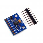
This is the one I have purchased: US9150.JPG
This is the Hobby Components Version:UK9150.jpg
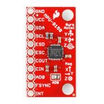
This is the Sparkfun 9150 (obviously different):Sprk9150.jpg
 
Last edited:
Did you know if the position of MPU (USB Arduino left and MPU right) has an impact on the yaw tracking? Because its work well but when I turn head to far to the left (usb left conf), the yaw axis turn automatically to 180° to the right. I thought maybe it's the position of the MPU that is not below the Arduino board no?

I auto-replied : I found an workaround solution : I put my EDtracker with USB rear but I let in EDTracker4 le USB Left config (pitch and roll are inversed). After that, I reconfigure this on opentracker! And thats work well :p
 
Magilag: Just quickly, that component on the hobby components board near The VCC pin socket is most likely a dc-dc step down chip which is why it will work with 5v. You should be able to find the 5v version on eBay relatively cheaply.

A workaround solution would be to incorporate a 3.3v linear voltage regulator or a step down yourself.
 
Last edited:
Magilag: Just quickly, that component on the hobby components board near The VCC pin socket is most likely a dc-dc step down chip which is why it will work with 5v. You should be able to find the 5v version on eBay relatively cheaply.

A workaround solution would be to incorporate a 3.3v linear voltage regulator or a step down yourself.

It looks like there is the same component on the version that I have, right?
 
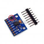
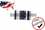
This the board you need and the red circle is the 5->3.3v LDO voltage regulator. I know this because I chop them off and bridge their input and outputs so that the board can work from the 3V battery in my wireless head trackers.

UK9150.jpg
 
Great! That's the one that I have :)

Can someone explain this to me?

"the MPU board you've specced there is 3.3v, not 5v, so you'll need to make up some arrangement to get the voltage down to 3v for it.
The 9150 boards we use (the 8-pin type) have a 3.3v LDO on them already so this doesn't present a problem
"

I'm a total noob when it comes to this stuff, so thanks for the help!
 
Last edited:
Sorry, One more question. Because I messed up the wiring the first time, I'd like to do it correct the 2nd.

Which is the correct wiring diagram?

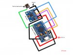
From BartyBee's Tutorial on the EDtracker website:
Bartycircuit2.jpg
Bartcircuit.jpgNote the PURPLE line from the switch on this?


From the EDTracker website:
edtracker_circuit_diagram.jpg
 
Great! That's the one that I have :)

Can someone explain this to me?

"the MPU board you've specced there is 3.3v, not 5v, so you'll need to make up some arrangement to get the voltage down to 3v for it.
The 9150 boards we use (the 8-pin type) have a 3.3v LDO on them already so this doesn't present a problem
"

I'm a total noob when it comes to this stuff, so thanks for the help!

As Kile pointed out, provided you MPU board has that little LDO on it, then it can run off the 5v that your USB line is supplying. My point was, the red SparkFun 9105 boards don't have that on them, as you discovered ;-)

Sorry, One more question. Because I messed up the wiring the first time, I'd like to do it correct the 2nd.

Which is the correct wiring diagram?

They are functionally identical; they are both correct ;) follow whichever one is easier for you. The purple line on Bartybee's doco is the same as the green line on the pictorial guide ;). What's probably throwing you is that, in Bartybee's diagram, you can't see the orientation of the MPU board as it's not shown, but it is turned 180 degree compared to the bottom pictorial guide... hence why it might seem like the pins are the wrong way round.
 
If the GUI "connects" but just doesn't show any movement (all values at zero or 62.75), no values changing just solid, but the graphs are trundling along nicely, then it does indeed suggest that the comms between the AVR and the MPU have given up the ghost. You could try putting the 6050 code into it temporarily just to see if that has any better luck, not really as a long-term solution but just to understand what aspects of the chip may not be working. But short of getting a DSO on the i2c lines, it's just the usual checking really :( which sounds like you've already done

Thanks Brumster for your reply.

I'll take it to work with me next week and wire it up to a DSO. See if I can find anything. In the meantime I've ordered another one in case I can't fix this one!
 
No worries. For your checks :

The 9150 code is so tightly squeezed in there, there's no option to flick between polling and interrupt drive like in the 6050, so it's hard-coded to int mode. Check if you're getting INT pulled low to signal data; the pulse width should be around 50uS and should be happening pretty much every 100ms in bursts of ~3.
 
Dull question - the kit from hobby components doesn't include the pcb does it? Need to order that separately from edtracker website?

I ask because they have a kit without the prototyping board, but not for the 9150 version.
 
I'd like to thank everyone who has been involved with ED Tracker - especially Becky for fulfilling my order, and Brumster for the excellent calibration video, but really to anyone who has contributed to the creation of this fine product.

I've just tried my new unit for the first time in game, and it is absolutely amazing....worked first time with no fuss.

Its a great addition to Elite - I love it. Thank you.
 
Back
Top Bottom