DIY Head Tracker For A Tenner

Sure, all I meant was that in Windows 7 (and I assume 8 and 10), you can click on a controller in "USB Game Controllers" and, in Properties->Settings for a device, there's a calibrate button. Don't be tempted to use this for EDTracker - it doesn't need it. If you ever do, just click the "Reset to Default" button and leave alone ;)

This - Windows game controller calibration really doesn't agree with EDTracker's inputs.
 
PS. This morning when re-calibrating the tracker closer to the real position of my head and carefully doing to turns, I think I got it working more reliably. However, the "shakiness" is still somewhat a problem. I have set deadzones in ED settings and some smoothing in tracker software, but still my head wopples like pear in a sentrifuge.. I doubt tho that my head is less balanced than the next guy's - are other experiencing this as well?

If you've got the scaling ramped up then that just exaggerates fine head movement. I personally use exponential, which gets rid of that nervousness around dead-ahead, but other people prefer linear with some smoothing. I personally find smoothing doesn't so a fat lot until it's up in the 80's+.... but YMMV ;)

- - - - - Additional Content Posted / Auto Merge - - - - -

6DOF - since most people probably monitor this thread, Rob's started a question for potential testers on a new thread, for those who want 6DOF....

https://forums.frontier.co.uk/showthread.php?t=231784
 
If you've got the scaling ramped up then that just exaggerates fine head movement. I personally use exponential, which gets rid of that nervousness around dead-ahead, but other people prefer linear with some smoothing. I personally find smoothing doesn't so a fat lot until it's up in the 80's+.... but YMMV ;)

While not being an "engineer" really, I didn't quite understand the difference between linear and exponential... Could you please post your settings regarding EDTracker settings so I could try one of those you professionals have set up? Thanks!

I will mess up a little more tonight while I get a chance to become a gamer-nerd again ;)

-v
 
Just click the scaling to Exponential instead of Linear - nothing more to it that that. The scaling values I have are 16 on both X and Y.
 
While not being an "engineer" really, I didn't quite understand the difference between linear and exponential... Could you please post your settings regarding EDTracker settings so I could try one of those you professionals have set up? Thanks!

I will mess up a little more tonight while I get a chance to become a gamer-nerd again ;)

-v

Exponential means that the further you move from centre the greater the movement. I.e move your head 1 degree from centre = screen moves 1 degree, move your head 2 degrees from centre = screen moves 4 degrees, move your head 5 degrees = screen moves 20 degrees, etc.
Linear means move your head 1 degree = screen moves 1 degree, 2 degrees = 2 degrees, 5 degrees = 5 degress, etc.

Personally i set a dead zone in ED and use linear, pitch/yaw at around 6-7, smoothing on 99.
I have to make quite large movements but I get a good amount of control and fine adjustment
 
Last edited:
Thanks brumster and sewerratuk (and for explanation of the exponential), will try meddling with the settings. So far I found the EDtracker as a good addition to game controls, I just wish to get it bit more steady and less drifty.

-v

PS. I eventually got it working well enough. I think the problem was with calibration rather than with the settings of game/GUI. I did the whole calibration process from the beginning, including keeping it on level surface and paying extra attention on the movements when calibrating. Now its much less shaky and drifty. I wonder how well the calibration could be done after all? But I don't dare to re-calibrate it again right now as it is working sufficiently well in my opinion.

Another question though - do you need to recalibrate EDtracker often, or are the auto-bias and reset view usually enough to keep it working?
 
Last edited:
The calibration doesn't need to be redone unless you don't play in different locations, because each location has a distinct magnetic environment.
 
Good to know. Thanks. At least my magnetic environment have remained same now for sometime, but who knows for how long? Maybe I can detect one too if my EDtracker goes nuts ;)

-v
 
I bought 2 set of arduino and gyro from hobbycomponent.
First one i solder it on regular board and didnt work. Not recognizing gyro input. the value jsut stuck in 0 and does not change. And temperature is like -2800 ish some times 9000 something... so i thought i made mistake on wiring and try to unsolder it but failed.

so i bought another one with PCB board from the website. soldered on the pcb but NOT WORKING.
NOTHING NO RESPONSE JUST LIKE THE FIRST ONE!
Temperature is acting weird, x gyro not recognizing.. same for y and z VALUE does not change at all.

I am out of ideas... plz help...
(Driver and the port is fine)
 
Stupid EDTracker Noob question...

Calibration : Done

Getting it to work in ED... ummm... Obviously missing something simple.

EDIT: Found a video with settings on YouTube
 
Last edited:
I was very impressed with the head tracking implications of this as I've tried (and failed) to get a IR tracker working with my existing webcam. Ordered a cheapish set of kit from china via ebay. Everything looked good when i got it, however I think I've got a physical problem with the hardware and since this is my first breadboard adventure i'm wondering if i can get some help.

The problem I am having is that while I can flash the Ardunio (GUI WORKS PERFECTLY UP TO FLASHING COMPLETE), it doesn't seem to be connecting to the MPU. The startup sequence when power is added is I get a solid red light and ONE flicker of a yellow light on the Ardunio itself, and NOTHING happens on the MPU board. No light at all.

This leads me to fear that it's a jumper issue or a problem with my breadboard technique, again total noob.

I used the pin advice from the ED Tracker website, as follows

All GND (3x on Ardunio and 1x on the MPU to a single row)
VCC >> VCC
Pins 2 & 3 >>> SCL & SDA

Pin 7 >>> Init

No button wiring so all others omitted. Total of 7 wire jumpers placed.

I opted to try to do this solderless, so the header pins are pinning the chips onto the breadboard but are not soldered to the breadboard.

Questions: 1) Will my lack of soldering be a problem? 2) Does my attached pictures indicate any obvious gaffes? 3) Is there any way to get a response from the MPU 9255 using a ohm meter or other File 2016-03-02, 10 48 34 PM.jpgFile 2016-03-02, 10 48 34 PM.jpgpower source etc to see if it actually is functional and not dead? 4) Is it possible to kill this hardware accidentally with a USB cable worth of power to its naughty bits? This is my first project with Arduino and so far it's been a learning experience.
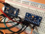
 
I opted to try to do this solderless, so the header pins are pinning the chips onto the breadboard but are not soldered to the breadboard.

Questions: 1) Will my lack of soldering be a problem?
I would bet good money this is the contributing problem, yes. You're probably not getting a good enough connection on the i2c lines, would be my guess.

2) Does my attached pictures indicate any obvious gaffes?
Nothing obvious from what can be made out, other than point 1 above ;)

3) Is there any way to get a response from the MPU 9255 using a ohm meter or other power source etc to see if it actually is functional and not dead?
Not really with a simple multimeter, no. You really need an oscilloscope to see traffic across the i2c bus. You can do some basic checks that you're getting 5v in to it, and 3.3v out of the voltage regulator - but I'd investigate 1 above first.

4) Is it possible to kill this hardware accidentally with a USB cable worth of power to its naughty bits? This is my first project with Arduino and so far it's been a learning experience.
Not really, no. You've got 5v going in, and the MPU board is 5v tolerant (it converts it down to 3.3v itself) so it shouldn't have a problem. The Pro Micro's also have a resettable fuse on them so any overcurrent and they'll self-reset... and that's if your PC doesn't do it first (most USB controllers will detect a heavy draw and shut the USB power down to the faulty device).
 
Last edited:
Also, a bit of news for people - we've revised the DIY PCB for the newer MPU-9250 boards. No functional difference really, just allows you to build with the larger MPU-9250 boards without having to leave off the button or take a file to your MPU board :)

There is a little potential feature on there for point tracking, for those homebrew builders willing to tinker a little more. It's really just a power source off the 5v USB line for those who know what they're doing, but we had the real estate on the board so it seemed sensible to throw it on there while we were at it. Completely optional, and I suspect most people won't be fussed for it.

DIY_V3_PCB_640x480.jpg
DIY_V3_Devices2_640x480.jpg
 
Last edited:
I did mine solderless (I did solder the pins to the boards, but other than that no solder) and it works just fine. I used a board that wasn't much bigger than the board itself though. I will post a pic when I get home.
 
Is it possible to do this with an MPU-9265 board?
Every ebay order for a 9250 has resulted in those and they don't seem to play nicely. They work after flashing as long as I don't unplug them. After a power cycle I need to reflash to make it work. It feels like it's short on cpu cycles but I don't have any suitable debugging tools/skills available.

Should this be working or not?

I've built two and get the same results on both. If I unplug and replug the device then try to connect from the ui I see the gyro calibration forever. If I dismiss that then the ui shows data but is jumpy and laggy.
 
Last edited:
I've seen a lot of boards "branded" 9265, this is really misleading by the Chinese knock-off shops that are making them as I've no idea what a 9265 is - it's certainly not an Invensense chip. The ones I've seen, they are all fitted with MPU-9250 chips so I've no idea where the manufacturers get the concept of "9265" from!

edit: We did a new firmware update for the 9250, v4.0.5, might be worth a try?

If the pin-outs on the board are the same, and the chip is a genuine MPU-9250, then it should work :( just avoid the SparkFun 3.3v boards; they don't have an LDO on the board and if you shove 5v into them, they won't like it ;). Fortunately it seems it's only Sparkfun in the US that are really selling these; 95% of boards I see are 5v tolerant boards (look for the little black LDO on them like this....)

SOT%2023-5.jpg
 
Last edited:
I can see the regulator on the board, and the unit does seem to be powered and functional. Mostly. I get the ideal mag calibration output and great behaviour in game just after flashing.
It just doesn't restart correctly on a power cycle until I re-flash.
Do you know if there is there anything about the reflash boot up that's different to the cold boot?

4.0.5 firmware has the same effect.

The chip on the board says "MP92" and something that looks like a serial number - the boards I have are all numbered differently.
I have a single working edtracker with a definitely genuine invensense mpu-9150 that actually says "invensense" on the chip. These 9265 boards don't say that on the chip.

If you have any interest in experimenting with these boards then I could stick some in the post. I've got a spare 9265 and one spare completely assembled with the arduino you can have.
 
The "boot" is all related to the Pro Micro of course, not the MPU board, but it might be the bootloader in your Pro Micro is in some way 'different' :-( dunno. I presume it shows up as an Arduino Leonardo?

Reflash "boot" will basically just tell it to restart the main image, and skip the bootloader, whereas a cold boot would enter via the bootloader. That issue around the booting suggests something up with the Pro Micro, or the boot loader image that's in it :( but I've never seen one behave like that in the flesh.

The MP92 is right - the mPU-9250 is a smaller chip so Invensense stopped putting their full name/logo on there, they just couldn't it it on :D so all MPU-9250's are just MP92 and some date code on the bottom (YYWW - YY = year, WW = week number). There's a middle number, not sure of the relevance of that.

I don't mind taking a look at them if you want to PM me. Will have a fiddle then send them back if/when I figure out what's up with them :)
 
Back
Top Bottom