I'll have a job! CEO of morale support, beer supplying and ideas!!
You are using an out of date browser. It may not display this or other websites correctly.
You should upgrade or use an alternative browser.
You should upgrade or use an alternative browser.
DIY Head Tracker For A Tenner
- Thread starter Dead Fred
- Start date
Stachel
Banned
Please put me down for one of these as well. £25+p&p? You should definitely do a kickstarter. There is clearly a huge stinky monopoly going on and the price of TrackIR is hideously over-inflated for what you get. You could probably create a genuine business from a simple stable product ..
This idea is not lost upon us.
If the government could tax thought, they would be well to tax Pocket and Brum. I myself prefer to appear a bit mental. It avoids the thought tax...
")
Is it not in the bible somewhere, thou shalt not think lest ye destabilise the status quo....
Maybe that's just my bible.
Strange how there are so many......
Perhaps they are all wrong?
If the government could tax thought, they would be well to tax Pocket and Brum. I myself prefer to appear a bit mental. It avoids the thought tax...
Is it not in the bible somewhere, thou shalt not think lest ye destabilise the status quo....
Maybe that's just my bible.
Strange how there are so many......
Perhaps they are all wrong?
Last edited:
I'm happy to pay for the completely made up kit, ready to strap on, plug in and shake about (complete working). I'm also happy to wait a while longer whilst you refine some more as you say DeadFred. It seems like an alternative little solution to having all the notrackIR gear stuck to my head and also using another webcam on the tv. I prefer this solution, and am happy to support it. The wireless option for the future sounds interesting also.
If your able and willing to make one up eventually for me please, that would be a kindness. I could I guess at a push assembly myself. But would rather someone who knows the device make it up.
I think I'd mount it in a custom cut velcro pouch on top of the headset band with cut out for the reset switch, with one or two other thin velcro straps to strain relieve the usb cable along the headset band. That way when listening to music I could quickly and safely remove the tracker and cable.
So yes I'm up for supporting the idea, and for waiting a while longer until your happier with the design and programming. Thanks.
Last edited:
Everything set up on a breadboard and mounted on my cap.
Works great. I can play for about 20-30 minutes before recalibrating. Sometimes it seems to get stuck with a slight offset to the right. Drift doesn't move further. I still need to play with the "responsiveness" values, but apart from that this is just great.
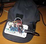
Wife had a laughing fit when she walked in on me with that on my head and pleaded to post a picture on Facebook. (NEVER).
<grins> Yeah... I bet she did!Wife had a laughing fit when she walked in on me with that on my head...
Everything set up on a breadboard and mounted on my cap.
Works great. I can play for about 20-30 minutes before recalibrating. Sometimes it seems to get stuck with a slight offset to the right. Drift doesn't move further. I still need to play with the "responsiveness" values, but apart from that this is just great.
Wife had a laughing fit when she walked in on me with that on my head and pleaded to post a picture on Facebook. (NEVER).
if i did 'facebalm'... i'd post it for you on your wife's behalf (-;
soo much better than most of the cxxp that's there
Last edited:
DIY “ED Tracker” - WHO WANTS ONE?
Here’s a marketing idea….If I knew how to do it - I'd post a poll: (gauntlet down!)
DIY “ED Tracker” - WHO WANTS ONE?
1: DIY ‘ED tracker’ for under a tenner PCB (printed circuit board) with instructions = £?
2: DIY ‘ED tracker’ for under a tenner PCB + components with instructions = £?
3: DIY ‘ED tracker’ PCB + components soldered to PCB with instructions = £?
4: DIY ‘ED tracker’ PCB + components soldered to PCB, flashed and programmed with instructions = £?
5: Not so DIY ED tracker programmed inc. instructions, micro UB lead (+ 3 metres) , Cobra Mk iii 3d printed case in gold lama + contract support for minimum term of 12 months payable by direct debit into a Swiss bank account (-: = £?
“ £ ? ” = make up price
Declare a closing date for the poll
Make the poll public so the names of votes can be recorded
PM (Personal Message) everyone who voted asking for FULL Payment via paypal detailing what they will receive within 3 months of payment - if they're lucky
Send out orders and declare everything to the tax man and do not accept any late orders.
Job done - retire to Southend, Essex. uk - for the weekend (-:
Personally.. id like to keep it DIY (they way it was intended) with good instructions, everyone can have fun and feel like they've conquered something.
Last edited:
Personally.. id like to keep it DIY (they way it was intended) with good instructions, everyone can have fun and feel like they've conquered something.
I think the same. For anyone who is really stuck I am sure there might be the odd volunteer who would be willing to put one together for somebody else.
After all, if you are making one then making 2 or even 3 at the same time does not take 2 or 3 times as long.
Ah The Cult, I remember seeing them at hammersmith Odeon 85 or 86, I forget now. Long time ago.
Everything set up on a breadboard and mounted on my cap.
Works great. I can play for about 20-30 minutes before recalibrating. Sometimes it seems to get stuck with a slight offset to the right. Drift doesn't move further. I still need to play with the "responsiveness" values, but apart from that this is just great.
Wife had a laughing fit when she walked in on me with that on my head and pleaded to post a picture on Facebook. (NEVER).
After a quick look at your picture I noticed you have the VCC linked to the other side of the Arduino and the MPU6050. You can remove that and have it going from the VCC to the MPU. As thats the only one needed.
Its the same with the ground links you only need the ones going to the other chip/ switch (but i can't talk as i also over corrected for that).
If found this schematic from brumster the best to work from.
Last edited:
After a quick look at your picture I noticed you have the VCC linked to the other side of the Arduino and the MPU6050. You can remove that and have it going from the VCC to the MPU. As thats the only one needed.
Its the same with the ground links you only need the ones going to the other chip/ switch (but i can't talk as i also over corrected for that).
If found this schematic from brumster the best to work from.

Interesting..
This schematic is not really a circuit diagram and is misleading.
If you analyze the designed and 'mass produced' ED tracker PCB the connections are different.
Are you saying that this PCB design will not work?
If a GND (ground) is marked I was always told it should be connected to GND. As for the other +ve (VCC) i have been informed it doesn't matter as it was a way to make the tracks possible on the pcb and makes no difference.