I'll report more once I know more.
Thankyou, please do. I also have some on order (I'm a cheapskate, so they are coming over from HK), but would love to hear what you find
I'll report more once I know more.
I have a 9150 in one. The DMP does *not* process the magnetometer readings and fuse them, or at least the firmware available doesn't and it's not documented how to get it to, so you have to manually read them and fuse it yourself. At least this was the result of my initial investigations - Pocketmoon can correct me if I'm wrong, the nav6 libs might be better with the newer MotionApps version....?
Invenses have backed away from offering full tripple sensor fusion either in the DMP (magical secret on-chip processing) or in any example code.
Magnetometer calibration is a whole world of interesting. Much trickier than acceleration and gyro. There is example arduino based code out there on github etc that does full sensor fusion but my worry is that it would introduce a lot more latency.
I do have a concept to try (when mine arrives from HK) that doesn't require mag calibration or additional fusion.
Sounds cool. My plan was to simply take a reference value at dead-ahead.../QUOTE]

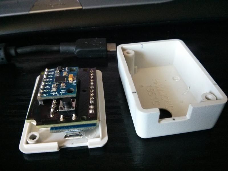
Finally soldered up the PCB - Board all works great!
Wondering if I'll be able to squeeze it into the earcup of a headset...
Thanks again guys.
So how does a poor exiled Irishman out in Yankeeland get his grubby wee paws on one of those PCBs?
Just drop me a PM, I'll add you to the list and then Brumster, dead fred or I will get back to you asap.


I been playing around with the new version of the tracker and while it is certainly easier to use, i have a current problem where by i look as far right or left as i can and the view shoots across to the opposite side?
anyone else seen this? Also i find when looking left and right to look at the panels i have to move to far left and am not really looking at the screen as i would like and looking down ever so slightly.
i calibrated on the table flat and let it monitor for just over an hour.
any ideas?
Edit : and using the latest version which includes the calibration fix, also EXPONENTIAL seems to make no difference to me whether in or out
here is a screen shot after an hour of monitoring


